Progress Evaluation
The hand in date is today and overall I am pleased with my progress. My model may not be a spitting image of me and the expression of the model is a bit gormless but generally I am happy with the current result. I think that it is easily recognisable as being me. There are still some weak areas in the model in my opinion, for one I don't think the nose is completely accurate to my own around the nostrils.
Texture wise I have already expressed my dissatisfaction with the quality of the original reference images and if I had known early on how important it had been I would have taken the time to take a high quality photo where all features of the face were visible. Because of the problems with the image my final texture is slightly lower quality than it could be and I have no decent texture for the ears.
At this stage I have yet to create a specular map for the model which could add even more to the realism of the texture. I plan to add this to the model over the next few weeks including, if possible a better texture for the ears.
I learnt a great deal during the last few weeks in terms of modelling techniques and how to effectively create textures. Being on the Computer Games Development course means that this module has been especially useful for me so far as I can apply my developing skills towards 3D modelling in video games.
Friday 21 October 2011
Modelling My Face - Adding Hair
Since the first deadline is today I have decided to quickly add some hair for a more finished look. Using the built in hair and fur modifier tool provides a quick and easy way of adding fairly realistic looking hair to a model. This is done by selecting the polygons on the model which produce hairs, in this case the all of the polygons on the top and back of the hair to the hair lines.

I then styled the hair to better match my own style by using comb and scale. I also quickly attempted to brush the fringe to one side as my usual hair style.

Im very impressed with the quality of the hair modifier tool. It looks quite realistic and even looks quite like my own style.
Here is a full high quality render of the model using a daylight lighting system and transparent shadows.

Modelling My Face - Bump Mapping
Bump mapping is used to create the illusion of depth in a texture. In this case the small bumps and contours in the skin. The process of doing so isn't very difficult and can really help make a texture look much more realistic. However the quality of the bump maps is dependant on the size and quality of the reference image used. This is slightly worrying as my reference image was not of the best quality.

I created the bump map above using the texture I had created previously in Photoshop. Grey areas in a bump map indicate flat areas whereas white and black indicate the rise and fall in the texture. The background of the image was set to a mid-level grey for the flat effect. I then removed the saturation from the image turning the image grey scale before applying the high pass filter changing the image to the one seen in the screenshot above. At this point the image can be used as a bump map. However the edges of the image have white lines around them. This would cause a bump in the texture along the symmetry lines. I fixed this using the rubber stamp tool and blending them slightly.
Applying this bump map to the facial texture adds all of the little bumps and grains from the bump map and applies it on top of the face texture.
 The bump map effect is most obvious here on the forehead and center of the chin. The low quality of the texture again can be seen on the side of the nose with some stretching unfortunatly.
Tweaking the bump map properties with a noise modifier reduces the density of the bumps in the bump map giving an even more realistic effect.

Close up the effect of the bump map is quite impressive.


I created the bump map above using the texture I had created previously in Photoshop. Grey areas in a bump map indicate flat areas whereas white and black indicate the rise and fall in the texture. The background of the image was set to a mid-level grey for the flat effect. I then removed the saturation from the image turning the image grey scale before applying the high pass filter changing the image to the one seen in the screenshot above. At this point the image can be used as a bump map. However the edges of the image have white lines around them. This would cause a bump in the texture along the symmetry lines. I fixed this using the rubber stamp tool and blending them slightly.
 |
| The final bump map |


Tweaking the bump map properties with a noise modifier reduces the density of the bumps in the bump map giving an even more realistic effect.
Close up the effect of the bump map is quite impressive.

Modelling My Face - Creating Textures Continued
Since the last post I have progressed further on the texturing process to the point where I just need to work on the eyes and ears.

It is at this stage that I have come across a major problem. I have no available texture for the ear. The original reference image had the ear partially covered by hair. As well as this the second image a took for when I first noticed this problem has gone missing with only a .jpeg of the image covered in reference guide lines. Not very useful for texturing. This means that to meet the current deadline I had to do the best with what I had.

Before that however I worked on the eye area. Using the normals render of the UV Map I drew around the areas of the eye which have the most depth. Indicated by the change in colour. This is the inner part of the eyelid. I filled this area in with the skin tone colour for the inside of the eye.

The screenshot above shows the final texture I have created. Not as good as I would have liked. The resolution is quite low due to the camera used to take it, secondly one side of the face is a different tone due to the lighting in the picture as well. Thirdly I had to be creative with the ear texture due to having no available reference image. I used a similar skin tone and some hair to blend it in.
This is how it looks in 3DS Max:

The ear definitely stands out with the low quality of the texture I made which is unfortunate as overall the texture doesn't look too bad. It lines up generally quite well. The final step now will be to add a bump and specular map and maybe add some hair as an extra bonus.
Modelling My Face - Creating Textures
Creating the texture for the face involves a very different set of skills within Adobe Photoshop. Using the original reference images and copying parts of the face over onto the UVW Unwrap guide rendered in the last section.

I first opened the rendered texture mapping guide in Photoshop and brought the guide through as a mask as seen above.

Using the guide I cut and pasted parts of the face roughly into the right position.

There are a few tools which can help shape the pieces such as the warp and liquefy tools. Warp (seen above) lets you move the pixels of the image around by the pivot points, stretching it where it needs to go. Liquefy works in a similar fashion but uses the cursor to push pixels around.

The next step is to merge the seams of the different peices using the tools available in photoshop. A very useful tool is the patch tool which grabs the texture of the any selected area and applies it to the previously selected area. This makes the different pieces blend almost seamlessly together.

Importing the texture into 3DS Max and applying to the model gives a good representation of how the texture is looking so far. Generally the texture lines up quite well on the model at this stage, some tweaks will be needed though.
Wednesday 19 October 2011
Modelling My Face - UVW Mapping Continued 2
I have now added the second unwrap modifier and positioned the mirrored polygons to be in line with the other half of the face.

I then welded the vertices in the center of the face together using the vertex weld. This process turns both sides of the face into one large texture.

The green lines show the edges of the texture. Where the vertices have been welded they have become grey. I welded the center vertices together and made sure they were aligned with the align X tool.
With the texture now fully unwrapped I can check to see how it looks by rendering it as an image. I set the aspect ratio high at 2048 by 1024 and rendered it giving the result below. This can be used later in photoshop to help create the texture itself.

Before continiung however I also rendered the UVW Map in normal mode. This shows the normals of the model in colour. It also shows overlapping polygons in red which in this case can be seen on the shoulders of my model which I must have missed earlier.

The offending polygon is a triangle shaped polygon with the lower vertices overlapping each other.

I quickly fixed the problem and now have a smooth unwrapped texture.

I also rendered a copy in shaded mode to see the effect:

Modelling My Face - UVW Mapping Continued
Because the ear is quite a complex shape I had to apply the same technique as I did to the head for the UVW Mapping.

I selected the ear polgons and rather then use the cylinder option like before I instead used the planer option and clicked fit to center in on the ear.


Clicking the pelt tool opens the pelt mode window and tools. This unwraps the complex model out into a flat shape making it much easier to texture. Selecting Start Pelt pulls the polygons outwards as seen above.

With the ear now flat for texturing I got the result seen above. The checkers are even and not stretched. However they are far too small so they need to be scaled to the right size.

Scaling down the ear in the unwrap UVW window to about actual size gives a more accurate checker size.

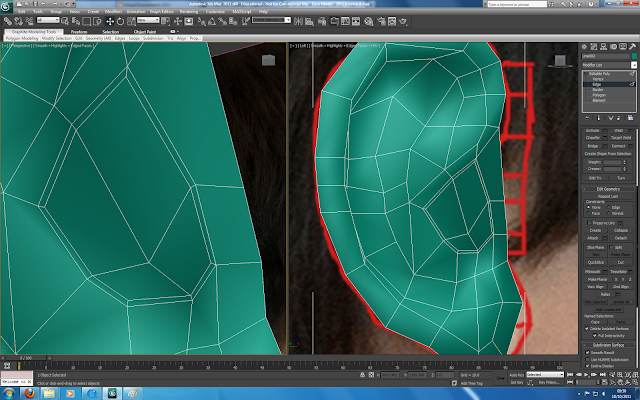
With the texture unwrapping almost done it is important to check that there are no inverted or overlapping polygons as this can cause problems with the final texture. When searching for inverted polygons the software found the one shown above by the ear. This is because the polygon is not a typical quad shape causing it to become inverted.

The screenshot above shows the texture flow at the moment. There are no inverted or overlapping polygons. The next step is to add another unwrap modifier after the symmetry to get a more accurate texture flow.

I selected the ear polgons and rather then use the cylinder option like before I instead used the planer option and clicked fit to center in on the ear.

The next step is to unwrap the model using the pelt tool. But before that I added a seem to the ear so it can unwrap easier by splitting apart at the seem. The seem is shown above by the faint blue line.

Clicking the pelt tool opens the pelt mode window and tools. This unwraps the complex model out into a flat shape making it much easier to texture. Selecting Start Pelt pulls the polygons outwards as seen above.

With the ear now flat for texturing I got the result seen above. The checkers are even and not stretched. However they are far too small so they need to be scaled to the right size.

Scaling down the ear in the unwrap UVW window to about actual size gives a more accurate checker size.

With the texture unwrapping almost done it is important to check that there are no inverted or overlapping polygons as this can cause problems with the final texture. When searching for inverted polygons the software found the one shown above by the ear. This is because the polygon is not a typical quad shape causing it to become inverted.

The screenshot above shows the texture flow at the moment. There are no inverted or overlapping polygons. The next step is to add another unwrap modifier after the symmetry to get a more accurate texture flow.
Tuesday 18 October 2011
Modelling My Face - UVW Mapping
Now that I have the general model for my head its time to think about texturing it. The first step for this is getting a UVW Map of the polygons that make up the head. Basically flattening out the model into an image that can be used as a guide later on when creating the actual texture.
I first started by adding a UVW Unwrap Modifier to model before the symmetry modifier already applied. Then I selected all of the polygons except around the ear which I can do seperately later. This is because the ear is a very complex shape and is easier to handle on its own.

With the polygons selected I then went into Cylinder mode and positioned the cylinder (shown above) so that it surrounded the head and lined up with the center of the face. This is for calculating where the texture will be applied.

Once that is done I went into edit mode which brought up the editing window seen above. At this stage a checker texture is shown on the model representing the texture flow.
In some areas the texture is stretched. This needs to be fixed otherwise then the actual texture is applied it will also look stretched.

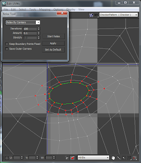
Selecting the vertices where the stretching is occuring and using the relax tool positions the vertices to better prvent stretching. This can be done manually but is acheived faster using this method.
I also used this method on common trouble areas such as the eye:

After some tweaking and some manual movement of vertices the final result looks quite good. The amount of stretching has been greatly reduced.
I first started by adding a UVW Unwrap Modifier to model before the symmetry modifier already applied. Then I selected all of the polygons except around the ear which I can do seperately later. This is because the ear is a very complex shape and is easier to handle on its own.

With the polygons selected I then went into Cylinder mode and positioned the cylinder (shown above) so that it surrounded the head and lined up with the center of the face. This is for calculating where the texture will be applied.

Once that is done I went into edit mode which brought up the editing window seen above. At this stage a checker texture is shown on the model representing the texture flow.
In some areas the texture is stretched. This needs to be fixed otherwise then the actual texture is applied it will also look stretched.

Selecting the vertices where the stretching is occuring and using the relax tool positions the vertices to better prvent stretching. This can be done manually but is acheived faster using this method.
I also used this method on common trouble areas such as the eye:


After some tweaking and some manual movement of vertices the final result looks quite good. The amount of stretching has been greatly reduced.
 |
| This screenshot was taken using the 2012 version of 3DS Max hence the slight difference in colour |
Monday 10 October 2011
Modelling My Face - The Ear Continued
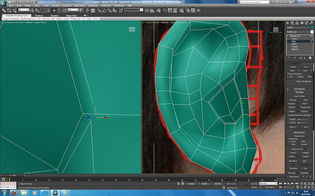
Continuing with the ear model I have begun modelling the back of the ear and the part where it joins onto the head.

I started by selecting the outer edges and extruding them out to add some depth to the ear. Then I extruded them inwards using the scale tool while holding shift.

In order to make attaching the ear to the head easier I had to reduce the amount of polygons leading from the ear to the head itself. I did this by creating polygons manually which is slightly visible in the screenshot above.

Next I deleted some polygons on the side of the head where the ear will be attached and lined up the vertices from the edge of the ear model to the head using vertices snap. I also had to manually create polygons (keeping them in quads) so that they line up correctly with the existing head vertices. Once lined up I attached the ear model to the head using the attach tool and did some tidying up.

The above screenshot shows how it looks with turbosmooth on. Not bad, it represents my ear fairly well and flows well due to the keeping all polygons in quads.
Modelling My Face - The Ear
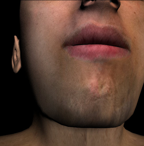
The first problem I came across when starting on the ear was my original reference image.
As you can see from the image majority of my ear is covered up by my hair. Having not known in advance I would be needing that part of the reference image it wasnt given any thought. I quickly took a new photo (making sure it was flat by using the lens distortion tool in Photoshop) and started adding the topology lines. Once complete I copied them to my original reference image.

With the reference image updated I reloaded the image in 3DS Max and started drawing the topology lines. I made sure before continuing that there were no triangles in the model. Just like with the beginning of the face I had to draw each polygon and then when finished attach them together. Then finish up by welding the vertices.

The next step involves adding depth to the model. I did this using both the front and left viewports and dragged out each vertices one by one to where it should rougly be represented by the reference image.

Once I had finished adding the depth and shape to the ear I selected the part of the ear which leads to the ear drum and used the champfer tool to get the extra lines seen below.

While useful this tool likes to add triangles to the topology and to counter that I had to select the offending edges and click collapse to collapse the edge down. This method is shown in the images below.
Eventually I ended up with the model below:

The general shape is pretty good so far albeit not perfect. The next step will be to add the back of the ear and attach it to the head.
 |
| Original |
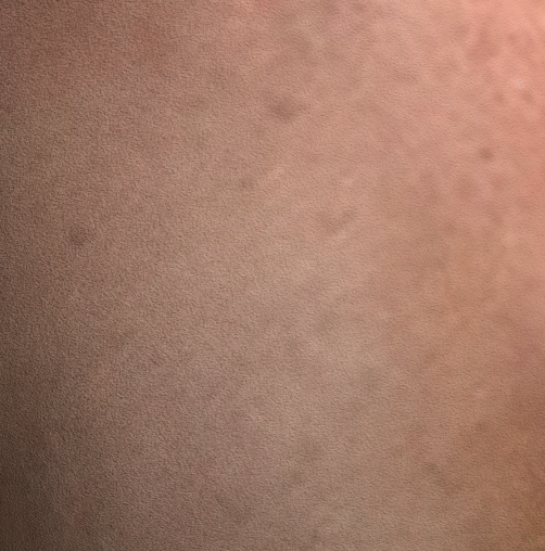
 |
| New Photo |

With the reference image updated I reloaded the image in 3DS Max and started drawing the topology lines. I made sure before continuing that there were no triangles in the model. Just like with the beginning of the face I had to draw each polygon and then when finished attach them together. Then finish up by welding the vertices.

The next step involves adding depth to the model. I did this using both the front and left viewports and dragged out each vertices one by one to where it should rougly be represented by the reference image.

Once I had finished adding the depth and shape to the ear I selected the part of the ear which leads to the ear drum and used the champfer tool to get the extra lines seen below.

While useful this tool likes to add triangles to the topology and to counter that I had to select the offending edges and click collapse to collapse the edge down. This method is shown in the images below.


Eventually I ended up with the model below:

The general shape is pretty good so far albeit not perfect. The next step will be to add the back of the ear and attach it to the head.
Subscribe to:
Posts (Atom)